#Autocad 2010 isometric drawing iso#
The view is drawn on the opposite end of the component from where the view was captured in first-angle projection.įirst angle projection is a ISO standard system and it is followed by european countries, whereas Third angle projection is followed by India, Canada, USA, Japan and many other countries. What is the difference between a first-angle and a third-angle projection?Ī component’s view is drawn adjacent to where it was captured in third-angle projection. Orthographic projection: A three-dimensional object representation approach via multiple views on different 2D reference planes. Isometric projection: The way by which three planes of a component are shown, portraying three-dimensional objects on the flat surface. What is the difference between orthographic and isometric projection?

We will mostly utilise the same commands we used during orthographic drawings. AutoCAD has certain tools, but not too many, that help us create the drawing.

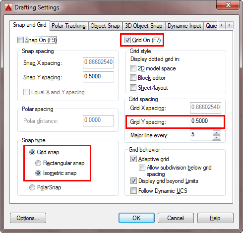
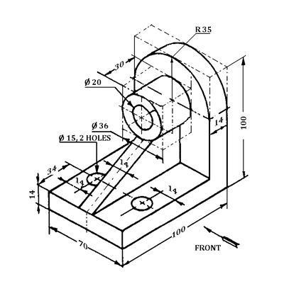
This method of drawing provides a fast way to create an isometric view of a simple design. Many times an isometric drawing is used to compliment a 3 view orthographic drawing. A 2D isometric drawing, which may be created from an isometric projection, is a flat representation of a 3D isometric projection. This has been the usual way of doing things before CAD allowed true 3-D work to be done. Copy and paste this 2D onto your isometric. Use change space (chspace) from the Express Tools to bring the 2D from model space to paper space. Next you can use 'solprof' to make a 2D drawing of it. Next, go to a layout and make a viewport and make it southwest-isometric. Different orthographic views to mention the Autocad orthographic projection are: Using Isometric commands is one of the simplest ways to give a 3-D representation while using only 2-D commands. Try this: Open a new drawing and create the ellipse in 2d then extrude it.


 0 kommentar(er)
